
Our Project

Software
Thor is programed using a Arduino Mega Micro-Controller, serving as the central brain that manages all its electronics functions within the arm. Our Lazy Suzan device that is used to rotate blocks is controlled by an Arduino Opta PLC. For more detailed information on our software, please consult the documentation tab.

Hardware
Explore our range of High-Quality components as seen in our bill of materials. Our rendition of Thor boasts top-of-the-line hardware, with four out of seven stepper motors being upgraded, this makes our arm more robust than Thor's original version.

SLA 3-D Printing Technology
The articulations in our arm were 3D printed using the SLA (Stereolithography process). This offers several advantages over using the standard method PLA (Polylactic Acid). SLA printing offers' higher resolution prints, capturing finer details with smoother surfaces. This makes the more complex pieces higher quality. Resin also has higher temperature resistance then PLA, Which withstands the heat produced by the stepper motors.

Conveyor Technology
Thunderclaw is proud to present a Lazy Susan device that will double as a conveyor system. Powered by Neema 17 motor equipped with a planetary gear box. The device utilizes two pulleys to generate seamless rotation. The design allows for circular movement enabling an efficient sorting progress by our robotic arm.
01
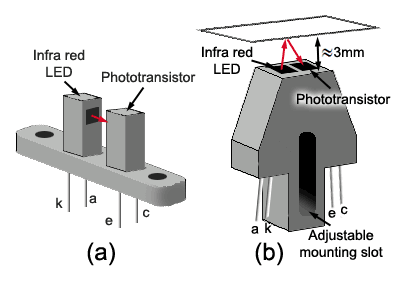
Optical Sensor
An Optical sensor is a device that uses light to detect the presence or absence of an object. It measures physical quantity such as distance, position, or speed. The sensor we chose is seen in the picture as option a).

02
Opto Disk
In this picture, you can see the Opto Disk. The thin layer of the Opto Disk sits in the center of the light-emitting diode (LED), moving in a circle until the light is no longer detected through the slit. This is able to tell us the "home" position of our arm.
03
The Articulation
In this picture, you can see where the opto disk fits, this allows the arm to rotate with the user having no worries of the arm exceeding its maximum rotation.

Individual Articulations
SLA Printing Technology

Articulation 1
This articulation is also referred to as the “base” articulation. This articulation is controlled by a stepper motor in the base of the arm. This motor spins a 3D printed gear which, in turn, spins the base. This allows the arm to rotate around a y-axis.

Articulation 2
Art 2 utilizes more 3D printed gears attached to motor shafts. This was the most challenging articulation to put together. Future groups could improve upon this design. This articulation spins the motors and causes the arms “shoulder” to be able to rotate.

Articulation 3
Art 3 utilizes a pulley and belt system. A motor spins a pulley and belt which end up rotating the arms “elbow.” There are belt cinchers located in the middle union which can tighten the belt to provide enough tension to allow the articulation to properly function.

Articulation 4
Art 4 uses a motor in the bottom of the top arm union. This motor uses the 3D printed gear method and turns the driveshaft. This allows the top union to rotate around the y-axis.

Articulation 5
Articulation 5 & 6 are the most complicated articulations. They are also connected to each other. Two gears, attached by the same rod, are connected to motors via belts and pulleys. These gears rotate the gear plate. When the gears are moving in opposite directions the claw will spin around the y-axis. When the gears are moving in the same direction, the claw will rotate around the x-axis.

Full Arm
When all the articulations are connected, it is now time to combine each articulation. All the articulations fit generally well. The most difficult part to assemble is the belt, if the belt is too loose, the belt will skip. This causes the arm to fall and not be able to be lifted. Once the arm is assembled we moved on to build the PCB.
PCB (Printed Circuit Board)
The printed circuit board our team utilized in our system was designed by none other than Angel LM, the creator behind "Thor". For a more detailed comprehensive breakdown, please check our detailed Bill of Materials, which can be found in the documentation tab. This PCB is housed with eight motor drivers, each dedicated to controlling the movements of its own stepper motor, along with a servo motor. The PCB establishes a direct connection with the Arduino Mega providing transmission of data generated by each optical sensor directly to our computer system.

Thor in action!
In the video below, you will see the early testing stages of Thor. This video was taking once the arm was constructed, and all the articulations were in a working fasion.

6 Degrees of Freedom
Autonomous
Open Source
Detailed instructions